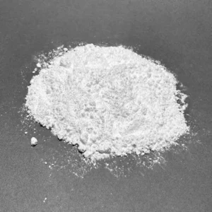
Graphite, molybdenum disulfide (MoS2) and PTFE can all reduce friction, but they do not solve the same tribology problem. Graphite and MoS2 rely on low-shear layered structures, while PTFE commonly works by building a polymer transfer film on the counterface. The right choice depends on atmosphere, contact pressure, sliding speed, temperature, electrical requirements and the mating surface. This guide gives design engineers a practical screening method and shows where Peflon’s graphite-filled PTFE, MoS2-filled PTFE and PTFE lubricant product lines fit. Final qualification still requires testing the complete friction pair under the intended duty cycle.
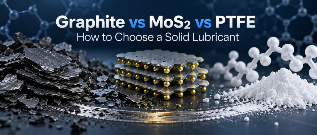
Graphite vs MoS2 vs PTFE: the short answer
Choose by the dominant failure risk, not by the lowest friction coefficient printed in a brochure. Graphite is often useful in air when a conductive, dark filler and improved heat transfer are acceptable. MoS2 deserves priority in dry or vacuum service and in heavily loaded boundary contacts, but humidity and oxidation must be considered. PTFE is attractive when chemical resistance, electrical insulation, cleanliness or quiet sliding matter, provided that creep, wear and transfer-film stability are checked.
| Selection question | Графит | MoS2 | PTFE |
|---|---|---|---|
| Primary lubrication mechanism | Low-shear sliding between carbon layers and formation of a lubricating film | Low shear between S–Mo–S layers and orientation of a solid-lubricant film | Low surface energy plus formation and replenishment of a polymer transfer film |
| Environment that usually favors it | Air or humid atmosphere; applications that tolerate black, conductive filler | Dry gas, inert atmosphere or vacuum; boundary lubrication under load | Chemically aggressive, electrically insulating or clean sliding systems |
| First limitation to check | Loss of lubricity in high vacuum; electrical conductivity and dark color | Humidity sensitivity and oxidation at elevated temperature in air | Creep, wear rate, PV limit and whether a stable transfer film can form |
| Peflon route | 5%, 10% or 20% graphite-filled PTFE | 5%, 10% or 20% MoS2-filled PTFE | Микропорошок PTFE, filled PTFE or Смазка PTFE |
How the three low-friction mechanisms differ
The three materials reduce interfacial shear in fundamentally different ways. Treating them as interchangeable “slippery powders” hides the variables that determine wear life.
Graphite depends strongly on its surface environment
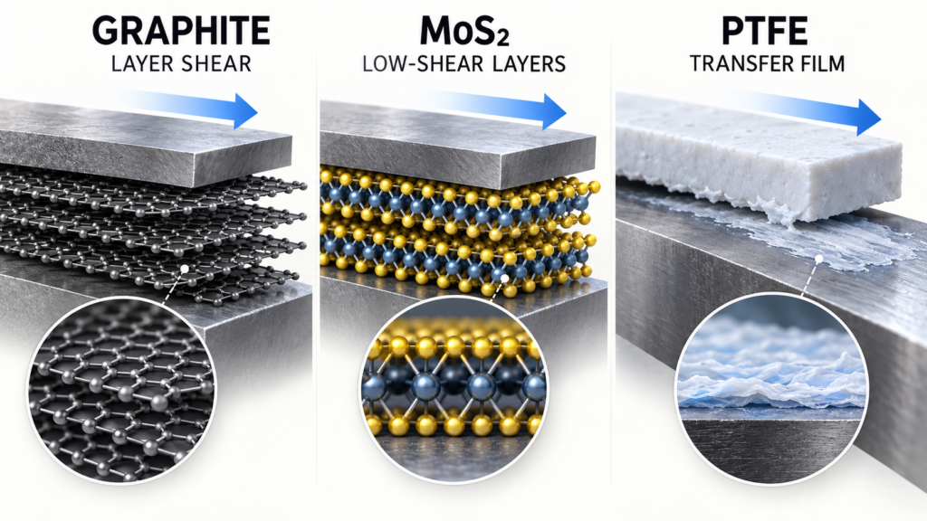
Graphite contains strongly bonded carbon sheets with much weaker interaction between adjacent sheets. That structure permits shear parallel to the layers. The practical complication is that adsorbed species, particularly water vapor, affect its friction behavior. NASA tribology references report that graphite friction rises as pressure is reduced and adsorbed water is removed; graphite can become ineffective or abrasive in space-vacuum mechanisms. This is why “graphite withstands heat” does not automatically mean “graphite works in vacuum.” See NASA’s discussion of microenvironment effects on graphite and MoS2.
MoS2 is a layered solid lubricant for dry and vacuum contacts
MoS2 is built from S–Mo–S sheets. Sliding can occur at the low-shear interface between sulfur-terminated layers. In dry gas and high vacuum, it can provide low friction without relying on the adsorbed moisture that graphite needs. The reverse boundary is equally important: water and oxygen can change film formation, while air oxidation becomes a life-limiting mechanism as temperature rises. MoS2 therefore needs an atmosphere specification, not just a temperature specification.
PTFE transfers material to the mating surface
PTFE is not a lamellar solid lubricant. Its fluorinated polymer chains produce low surface energy, and sliding commonly deposits a thin PTFE-rich transfer film on the counterface. Once established, the contact can shear through that low-friction film instead of continually exposing virgin metal. NASA testing of PTFE composites shows that wear performance depends on whether the transfer film forms, adheres and survives; adding PTFE can maintain a lubricating transfer film, but film failure or poor bonding raises wear. The NASA PTFE composite study is useful because it separates low friction from low wear.
What Peflon actually supplies for these routes
Peflon’s relevant offer is not one universal “solid lubricant grade”; it is a set of different material forms for different conversion routes. For molded or machined bearing and sealing parts, Peflon supplies graphite- or MoS2-filled PTFE compositions. For additive and surface-film applications, the route may instead begin with PTFE micropowder or a PTFE lubricant formulation.
| Peflon product line | Verified stocked options | Typical conversion route | Use it to screen for | Do not assume |
|---|---|---|---|---|
| PTFE с графитовым наполнением | 5%, 10% and 20% graphite filling | Molded stock, rod, sheet, seal or machined part | Dry-running sliding parts in air, thermal dissipation, dimensional stability | That it remains lubricious in high vacuum or electrically insulating |
| MoS2-Filled PTFE | 5%, 10% and 20% MoS2 filling | Molded stock, rod, sheet, seal or machined part | Loaded sliding or rolling contacts, dry-film lubrication, creep improvement | That air oxidation and humidity are irrelevant |
| Микропорошок PTFE | Grade selected by particle size and host formulation | Compounding into plastics, coatings, inks or lubricants | Friction reduction, release and transfer-film support | That one loading level works across every resin or coating |
| PTFE Lubricant | Solid, liquid and paste formats | Applied dry film, spray or grease/paste system | Clean sliding, chains, gears and mechanisms needing an applied lubricant | That the PTFE limit equals the carrier fluid’s limit |
The percentages above describe Peflon’s current product-line options shown on the corresponding product pages; they are not a universal ranking in which more filler is always better. Higher filler loading can change processability, elongation, sealing conformity and mating-surface behavior. Request the applicable TDS and test a representative part before locking the composition.
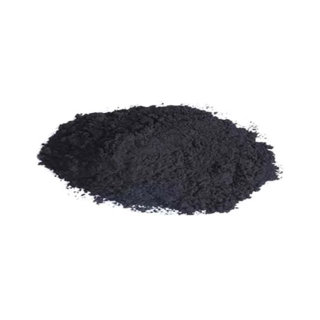
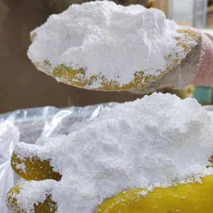
PTFE с 10% графитовым наполнением
A verified Peflon product-line image for the middle graphite loading. Use it as a trial starting point only after load, speed, atmosphere and electrical constraints are known.

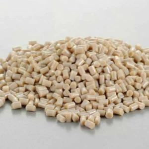
10% MoS2-Filled PTFE
A verified Peflon product-line image for the middle MoS2 loading. Vacuum suitability still depends on the complete compound, counterface and duty cycle.
Start the selection with atmosphere and temperature
Atmosphere is the fastest way to eliminate a wrong solid lubricant. High vacuum or very dry gas moves MoS2 toward the top of the shortlist and usually moves graphite down it. Normal air can support graphite’s lubrication mechanism, while humid air may make MoS2 film behavior less favorable. PTFE can operate in vacuum systems, but the design must check outgassing, wear debris and whether the counterface accepts a durable transfer film.
Use the real contact temperature, not the room or oven setpoint. Flash temperature at asperity contacts can exceed the surrounding temperature. PTFE’s polymer stability does not guarantee that a liquid carrier, binder or host resin will survive. MoS2 can oxidize in hot air. Graphite can tolerate high bulk temperature, yet its resin matrix may soften, creep or degrade first. The system limit is set by the first component to fail.
Then separate load, speed and motion pattern
A single PV number is a screening tool, not a complete tribology specification. The same pressure-times-velocity value can describe high-load slow sliding or low-load fast sliding, even though heat generation, film renewal and deformation are different.
- High load and low speed: prioritize compressive creep, boundary-film strength and extrusion from the contact. Graphite- or MoS2-filled PTFE may outperform unfilled PTFE, but the counterface and edge geometry remain critical.
- Continuous higher-speed sliding: check interface temperature, heat removal and steady-state wear. Low initial friction is not enough if the transfer film cannot be replenished.
- Short-stroke reciprocation or micro-motion: check whether the stroke is long enough to distribute a transfer film. PTFE can reduce noise and stick-slip, but a very short stroke may trap debris in one contact zone.
- Start-stop mechanisms: evaluate breakaway friction and run-in separately from steady operation. A material that performs well after film formation can still fail during repeated starts.
Use electrical, color and cleanliness requirements as hard filters
Secondary requirements often decide the material before tribology testing begins. Graphite can make a compound darker and more conductive, which may disqualify it for an insulating component. MoS2 also creates a dark compound and demands careful assessment where contamination or oxidation products matter. PTFE is usually the easier starting point for electrical insulation, pale-color systems and chemical inertness, but the complete formulation—not the polymer name alone—must satisfy the application requirement.
Food-contact and medical claims must be checked at grade and end-use level. A generic statement that “PTFE is food safe” does not qualify a filled compound, carrier, processing aid or finished part. Ask for the documentation applicable to the exact composition and destination market.
A practical solid-lubricant selection workflow
The safest sequence is environment, contact mechanics, exclusions and then material trials. This prevents a familiar mistake: choosing the lowest laboratory friction value before defining the actual friction pair.
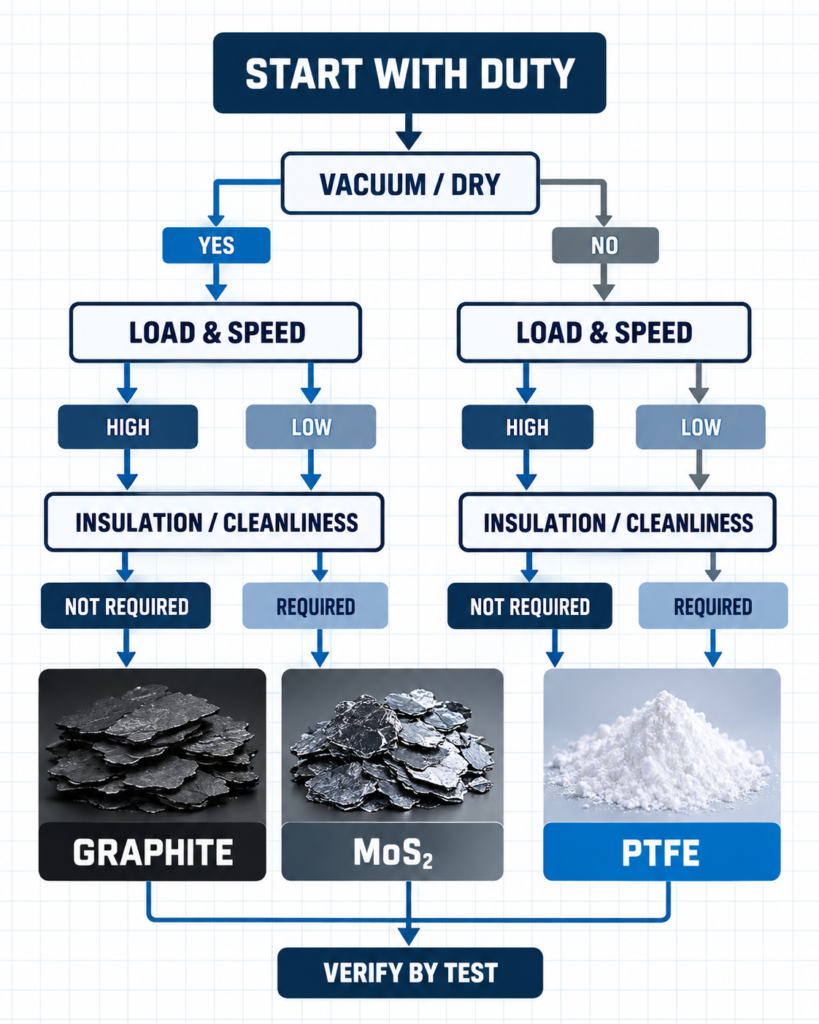
- Define atmosphere: air, humidity range, inert gas, vacuum level or chemical exposure.
- Define contact: counterface material, hardness, coating and surface roughness.
- Define duty cycle: pressure, speed, stroke, starts, duration and allowable temperature rise.
- Apply hard exclusions: electrical insulation, color, cleanliness, food-contact documentation and dimensional stability.
- Select two or three candidate compositions rather than one assumed winner.
- Run representative wear testing and inspect friction trace, mass loss, dimensional change, transfer film and counterface damage.
Common selection mistakes
Most failures come from treating friction coefficient as a fixed material property. It changes with load, speed, humidity, temperature, counterface, roughness and test duration.
Mistake 1: selecting graphite for vacuum because it is “high temperature”
Graphite’s thermal stability and its vacuum lubricity are separate questions. In a dry vacuum contact, the missing adsorbates that help graphite shear can make it the wrong choice.
Mistake 2: treating low PTFE friction as proof of long wear life
A PTFE-rich surface can start with low friction and still wear rapidly, creep out of the contact or lose its transfer film. Measure wear and dimensional stability alongside friction.
Mistake 3: specifying “10% filler” without controlling the rest of the system
Filler percentage alone does not define performance. Particle characteristics, dispersion, PTFE base resin, molding and sintering, part geometry, counterface and surface finish all affect the result. Supplier substitution should therefore include part-level requalification.
Часто задаваемые вопросы
Is MoS2 always better than graphite in vacuum?
Нет. MoS2 is normally the stronger starting candidate because its low-shear mechanism does not depend on adsorbed moisture, but coating method, binder, purity, contact stress, temperature and life requirement still determine the result.
Can graphite-filled PTFE remain electrically insulating?
Do not assume it will. Graphite is conductive, and conductivity depends on loading, dispersion and the percolation path through the compound. Request measured electrical data for the exact composition if insulation is a design requirement.
Does a higher filler percentage always improve wear resistance?
Нет. More filler may increase hardness or reduce deformation, but it can also change toughness, sealing conformity, processing and counterface wear. Peflon offers 5%, 10% and 20% graphite or MoS2 options so the loading can be qualified against the actual duty rather than selected by percentage alone.
Can PTFE micropowder replace graphite or MoS2 in any plastic compound?
Нет. PTFE micropowder supplies a different film-forming mechanism and must be matched to the host resin, processing temperature, dispersion method and target wear mode. It is an alternative route, not a drop-in equivalent.
What information should I send before requesting a sample?
Send the base resin or part form, counterface, contact pressure, sliding speed or stroke, temperature, atmosphere, target life, allowable wear, color and electrical requirements. Peflon can then recommend a graphite-filled PTFE, MoS2-filled PTFE, PTFE micropowder or PTFE lubricant trial route and respond within 24 hours.
Which laboratory result should decide the final material?
No single result should decide it. Review steady and breakaway friction, wear rate, dimensional change, transfer-film stability, counterface damage and thermal behavior after a representative duty cycle.
Request a grade-matched trial
Peflon can narrow the trial matrix once the friction pair and operating envelope are defined. Send your load, speed, atmosphere, counterface, temperature, target life and drawing. We will recommend the relevant filled-PTFE or PTFE-additive route, provide available TDS documentation and arrange qualification samples. Связаться с Peflon for a response within 24 hours.