Polyetheretherketone (PEEK) is a high-temperature engineering polymer used when standard plastics cannot meet heat, chemical, wear, or dimensional requirements. But the final quality of a PEEK part depends on more than the material grade.
Processing matters.
This guide explains common PEEK defects in extrusion, injection molding, compression molding, FDM 3D printing, and CNC machining. It is written for buyers, R&D teams, supply chain managers, product managers, distributors, and downstream manufacturers who need stable production, fewer rejects, and clearer material selection.
PEEK has a melting point of about 343°C, according to Wikipedia’s overview of polyetheretherketone. That high melting point helps in demanding applications, but it also makes the process window narrower than many standard engineering plastics.
At Peflon, we supply matériau PEEK for injection molding, extrusion, compression molding, compounding, and machining applications. We also support related high-performance polymers, including Dispersion de PTFE et Matériaux PFA.
Why PEEK Processing Needs Careful Control
PEEK is a semi-crystalline thermoplastic. Its crystallinity, cooling rate, and thermal history can affect strength, shrinkage, surface finish, and dimensional stability.
For purchasing teams, this matters because rejects are expensive. For R&D teams, test data from one trial may not match mass production if the process changes. For supply chain managers, a stable grade also needs to fit the customer’s equipment and production cycle.
Key processing factors to check:
- Drying: moisture can cause bubbles, voids, rough surface, and unstable flow.
- Temperature control: PEEK needs high heat, but excessive temperature or long residence time can cause carbonization.
- Pressure and packing: insufficient pressure can cause sink marks, voids, or incomplete filling.
- Cooling and annealing: rapid cooling can increase internal stress and dimensional movement.
- Tooling and fixtures: PEEK expands more than metal and can deform under high clamping force.
Point clé : PEEK processing is a material-and-process match. One parameter change may help, but stable production usually requires a full process review.
1. PEEK Extrusion Problems and Fixes
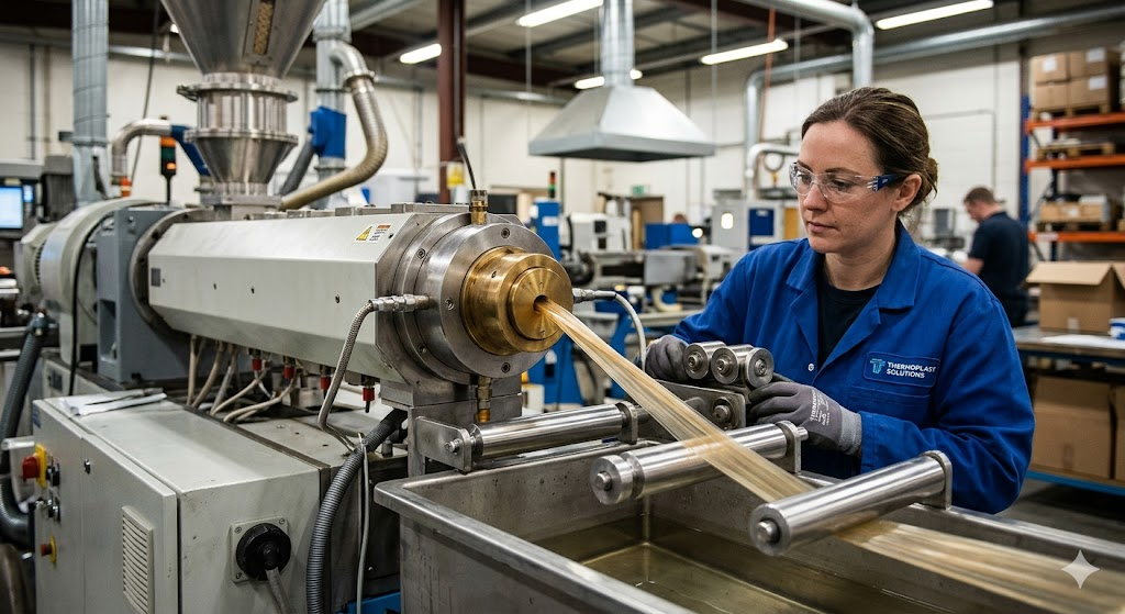
PEEK extrusion is often used to produce rods, sheets, tubes, profiles, and other semi-finished shapes. These parts may later be machined into seals, bushings, bearings, pump parts, or precision components.
Surface Roughness or Unmelted Particles
A rough surface with white or unmelted particles usually means the melt is not fully plasticized.
Common causes:
- Barrel or die temperature is too low.
- Die flow channel is too large.
- Die was not fully preheated before startup.
- Residence time is uneven across the melt stream.
Practical fixes:
- Increase barrel and die temperature within the recommended range.
- Reduce oversized die channel volume where possible.
- Improve melt mixing before the die.
- Preheat the die fully before stable production begins.
Orange Peel Surface
Orange peel texture looks uneven and dull. It often points to poor melt flow, a rough die surface, or cooling that is too aggressive.
Common causes:
- Melt temperature is too low.
- The surface is dirty, worn, or not polished.
- Cooling is too fast after extrusion.
- Material is exposed to uneven temperature zones.
Practical fixes:
- Increase the material or die temperature moderately.
- Clean and polish the die surface.
- Avoid sudden quenching.
- Use staged cooling to reduce internal stress.
Voids or Porosity
Voids may appear inside the profile or near the surface. They can reduce mechanical strength, sealing reliability, and long-term service life.
Common causes:
- PEEK resin was not dried enough.
- Moisture or volatiles were trapped inside the melt.
- The forming pressure was too low.
- The outer layer cooled too quickly and sealed the gas inside.
Practical fixes:
- Dry PEEK before extrusion. A common starting point is 150°C for 3–4 hours, but always follow the supplier datasheet.
- Use gradual heating to release moisture and trapped gas.
- Increase the forming pressure to compact the melt.
- Store resin in sealed packaging before production.
Black Spots or Black Core
Black spots, black lines, or a dark core are usually signs of carbonized material.
Common causes:
- Dead zones in the barrel, screw, adapter, or die.
- Excessive processing temperature.
- Long residence time.
- High pressure is causing local overheating.
- Fiber-filled grades generate extra heat under high shear.
Practical fixes:
- Clean the barrel, screw, and die after production runs.
- Avoid excessive temperature settings.
- Reduce residence time during startup and shutdown.
- Control head pressure.
- For glass-filled or carbon-filled PEEK, reduce unnecessary shear.
Spiral Marks in Rod Extrusion
Spiral marks inside a PEEK rod may follow the screw direction. They can affect internal uniformity and mechanical consistency.
Common causes:
- Melt flow remains rotational after leaving the screw.
- Die straight land is too short.
- Screw or barrel wall has contamination.
- Melt pressure is not stable before the die.
Practical fixes:
- Add or improve a breaker plate.
- Increase die land length.
- Clean the screw and barrel carefully.
- Stabilize melt pressure before full production.
Point clé : In PEEK extrusion, surface quality and internal structure both matter. A clean flow path, stable heat profile, and controlled cooling plan are essential.
2. PEEK Injection Molding Problems and Fixes
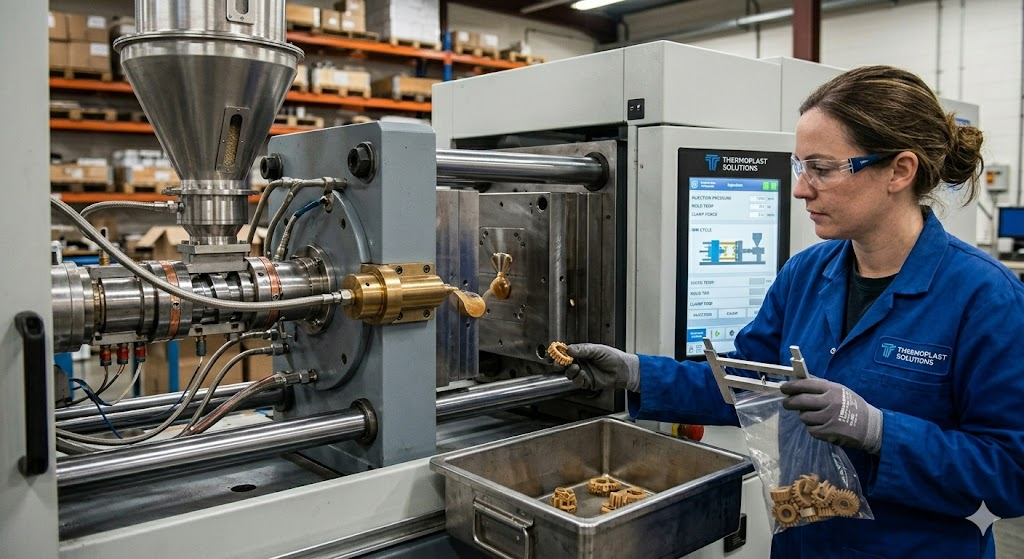
Injection molding is suitable for complex PEEK parts with tight geometry, thin sections, ribs, holes, and mounting features.
Yellowing, Darkening, or Black Spots
Color change or black particles often mean thermal degradation or contamination.
Common causes:
- Barrel or runner temperature is too high.
- Material stays in the barrel too long.
- Screw and barrel have carbonized residue.
- Resin was not dried before molding.
- Injection speed creates excessive shear heat.
Practical fixes:
- Lower barrel or runner temperature if degradation is suspected.
- Clean the screw and barrel before running PEEK.
- Match shot size to the machine to control residence time.
- Dry resin before molding.
- Adjust injection speed based on part structure and gate design.
Sink Marks and Shrinkage
Sink marks usually appear in thick sections or behind ribs.
Common causes:
- Holding pressure is too low.
- Holding time is too short.
- Gate freezes before the part is fully packed.
- Gate is too small or placed away from thick sections.
- Wall thickness varies too much.
Practical fixes:
- Increase holding pressure.
- Extend holding time.
- Adjust melt temperature.
- Increase gate size where needed.
- Place the gate near thicker areas if the design allows.
Weld Lines and Weak Areas
Weld lines often appear where two melt fronts meet, such as around holes or multi-gate flow paths.
Common causes:
- Mold temperature is too low.
- Melt front temperature drops before meeting.
- Air is trapped at the weld line.
- Gate position creates a weld line in a loaded area.
- Melt flow path is too long or unbalanced.
Practical fixes:
- Increase mold temperature.
- Increase melt temperature and injection speed within safe limits.
- Improve mold venting.
- Move weld lines away from high-load areas.
- Add overflow wells where practical.
Short Shot or Incomplete Filling
PEEK has high melt viscosity, so thin-wall or long-flow parts can fail to fill.
Common causes:
- Injection pressure is too low.
- Injection speed is too slow.
- Mold temperature is too low.
- Shot size is insufficient.
- Gate or runner dimensions restrict flow.
Practical fixes:
- Increase injection pressure and injection speed.
- Raise mold temperature to reduce early freezing.
- Check shot size and machine capacity.
- Enlarge gate and runner dimensions if needed.
- Add venting to reduce trapped air resistance.
Warpage and Deformation
PEEK warpage is closely linked to crystallinity, uneven cooling, residual stress, and unbalanced filling.
Common causes:
- Mold temperature is uneven.
- Front and rear mold temperature difference is too large.
- Holding pressure creates excessive residual stress.
- Gate layout is unbalanced.
- Cooling time is too short.
Practical fixes:
- Keep mold temperature uniform.
- Control mold temperature difference within a narrow range.
- Adjust holding pressure and holding time.
- Use balanced gate design.
- Extend cooling time before ejection.
Point clé : For PEEK injection molding, mold temperature and residence time are two of the most important checks.
3. PEEK Compression Molding Problems and Fixes
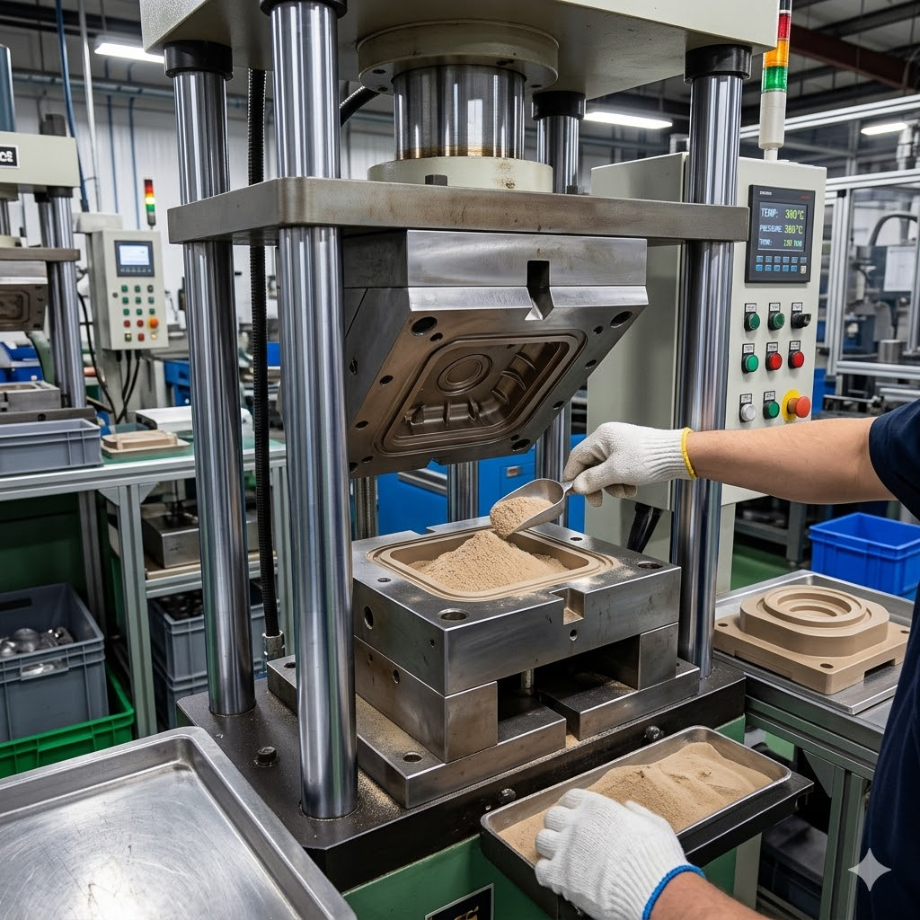
Compression molding is often used for PEEK sheets, rods, blocks, and parts that need high material use or special dimensions.
Voids or Vacuum Holes
Voids inside molded sheets or rods can reduce mechanical strength and sealing reliability.
Common causes:
- Material was not dried enough.
- Moisture or air was trapped during loading.
- Cold press or hot press pressure was too low.
- Heating profile did not allow trapped gas to escape.
Practical fixes:
- Dry PEEK powder or resin thoroughly before molding.
- Keep moisture as low as practical before loading.
- Increase cold press and hot press pressure.
- Use staged pressure to help remove internal gas.
Flash and Edge Material Loss
Flash can release pressure from the mold. When that happens, the center of the part may become underfilled or less dense.
Common causes:
- Mold clearance is too large.
- Pressure is lost through excessive flash.
- Mold closing speed is too slow.
- Pressing speed is not stable.
Practical fixes:
- Control mold clearance, often around 0.05–0.10 mm depending on tool design.
- Use spacers to control part thickness.
- Close the mold before the melt loses flow.
- Maintain steady pressure and press speed.
Cracking During or After Demolding
Compression molded PEEK can have high internal stress because of crystallinity and cooling history.
Common causes:
- Part is demolded while too hot.
- Cooling is too fast.
- Annealing is not controlled.
- Mold contact surfaces create high demolding force.
Practical fixes:
- Use slow annealing after molding.
- Avoid forced demolding above 150°C.
- Polish mold contact surfaces.
- Cool in a controlled way instead of rushing the cycle.
Surface Carbonization or Contamination
Blackened, bubbled, or dirty surface areas often come from long heating time, dirty tooling, or material contamination.
Common causes:
- Heating time is too long.
- Mold surface is not clean.
- Drying oven contains dust or residue.
- Material is exposed during loading.
Practical fixes:
- Control heating time carefully.
- Clean molds before production.
- Keep drying equipment and loading tools clean.
- Store PEEK material in sealed, dry packaging.
Point clé : Compression molding defects are often hidden inside the part. Good drying, pressure control, and annealing help reduce internal failures before machining begins.
4. PEEK 3D Printing Problems and Fixes
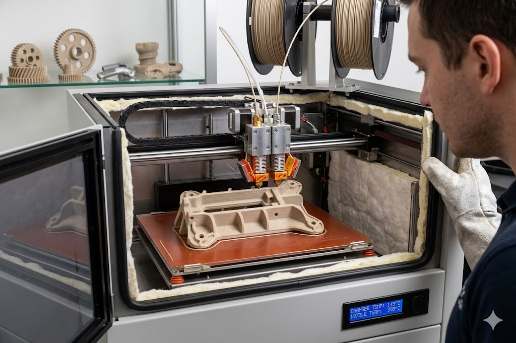
PEEK FDM printing is used for prototypes, low-volume parts, fixtures, medical models, and custom industrial components.
A typical desktop printer for PLA or ABS is not enough.
Layer Delamination
Layer delamination happens when printed layers do not bond well.
Common causes:
- Chamber temperature is too low.
- Temperature difference between layers is too large.
- Printing speed is too fast.
- Nozzle temperature is below the filament’s recommended range.
Practical fixes:
- Use a heated chamber. A chamber temperature of 90°C or higher is often needed, and 120°C or higher is preferred when the printer allows.
- Reduce printing speed.
- Increase nozzle temperature based on filament guidance.
- Anneal printed parts after printing to improve layer bonding.
Warping or Bed Detachment
PEEK shrinks as it cools. Corners can lift, and the model may detach from the build plate.
Common causes:
- Bed temperature is too low.
- Build surface does not grip PEEK well.
- Part corners cool too quickly.
- Contact area between part and bed is too small.
Practical fixes:
- Use a PEI build surface or high-temperature adhesive.
- Keep bed temperature around 140–160°C when equipment allows.
- Add a brim to increase bed contact.
- Avoid placing sharp corners directly on the build plate.
Support Removal Difficulty
PEEK support structures may bond too strongly to the part.
Common causes:
- Support Z-distance is too small.
- Support material is the same PEEK grade as the part.
- Overhang design requires too much support.
- Print orientation creates hard-to-reach support areas.
Practical fixes:
- Use soluble support if the printer supports it.
- Adjust support Z-distance to about 0.2–0.3 mm as a starting range.
- Redesign the part to reduce overhangs.
- Use self-supporting angles where possible.
Nozzle Clogging
Clogging can stop the print or create uneven extrusion.
Common causes:
- Filament contains moisture.
- Heat creeps upward and softens filament too early.
- Nozzle is worn by carbon fiber reinforced PEEK.
- Printer sits idle at high nozzle temperature.
Practical fixes:
- Dry PEEK filament at 120–150°C for about 4 hours before printing.
- Use hardened steel or wear-resistant nozzles for filled PEEK.
- Check heat-break cooling.
- Avoid long idle periods at high nozzle temperature.
Point clé : PEEK 3D printing depends on temperature consistency. Chamber heat, bed heat, dry filament, and post-print annealing all affect the final part.
5. PEEK Machining Problems and Fixes
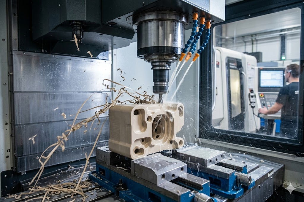
PEEK rods, sheets, and molded blanks are often CNC machined into precision parts. Compared with metals, PEEK has lower stiffness and higher thermal expansion.
Ensinger’s PEEK machining information also notes the importance of proper machining conditions for dimensional control.
Fast Tool Wear
Glass-filled and carbon-filled PEEK are abrasive. Standard tools may wear quickly, causing size drift and poor finish.
Common causes:
- Tool coating is not suitable for filled PEEK.
- Cutting speed is too high.
- Tool edge is dull.
- Chips are not removed cleanly.
Practical fixes:
- Use diamond-coated or CVD diamond tools for filled grades.
- For reinforced PEEK, keep cutting speed around 100–200 m/min as a practical starting range.
- Use climb milling to reduce rubbing.
- Replace tools before wear affects tolerance.
Burrs and Flash
Burrs often appear at hole exits, thin edges, and milled corners.
Common causes:
- Cutting edge is dull.
- Feed is too high at drill breakthrough.
- Part wall is thin or unsupported.
- Final pass leaves too much heat at the edge.
Practical fixes:
- Keep tools sharp.
- Reduce feed before drill breakthrough.
- Use step drills where suitable.
- Leave about 0.1 mm for a final finishing pass when accuracy is needed.
- Use controlled tool paths for thin edges.
Dimensional Change After Machining
A part may measure correctly on the machine, then change after unclamping or storage.
Common causes:
- PEEK expands more than metal under heat.
- The part was measured before temperature stabilized.
- Clamping force caused elastic deformation.
- Internal stress was released after machining.
Practical fixes:
- Use coolant or air cooling to control heat.
- Keep inspection temperature consistent.
- Avoid excessive clamping force.
- Rough machine first, then stress-relief anneal.
- Finish machine critical dimensions after annealing.
Rough or White Machined Surface
A rough, fish-scale, or whitened surface may come from heat buildup, tool wear, or poor chip removal.
Common causes:
- Heat is not removed fast enough.
- Chips wrap around the tool or re-cut the surface.
- Tool is dull.
- Feed per revolution is too high.
Practical fixes:
- Use coolant or air cooling.
- Clear chips during machining.
- Increase spindle speed and reduce feed per revolution.
- Use diamond tooling for high-quality surface requirements.
Point clé : PEEK machining is not the same as metal machining. Temperature, clamping, tool sharpness, and stress relief have a direct effect on final dimensions.
How to Choose the Right PEEK Grade
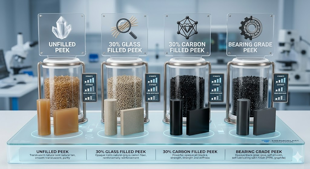
Different PEEK grades behave differently in processing. A grade that works well for injection molding may not be the best choice for machining or 3D printing.
Virgin PEEK
Virgin PEEK is used when purity, toughness, chemical resistance, and clean surface finish are important.
Common uses:
- Medical and laboratory components
- Electrical insulation parts
- Precision housings
- Chemical-resistant components
Glass-Filled PEEK
Glass-filled PEEK improves stiffness and dimensional stability.
Common uses:
- Pump and compressor components
- Structural brackets
- High-temperature fixtures
- Molded industrial parts
Carbon-Filled PEEK
Carbon-filled PEEK offers higher stiffness, lower thermal expansion, and better wear behavior than virgin PEEK.
Common uses:
- Roulements et bagues
- Sliding components
- Aerospace and automotive parts
- Precision-machined components
ESD or Conductive PEEK
ESD PEEK is used where static control matters.
Common uses:
- Semiconductor fixtures
- Electronics handling parts
- Test sockets
- Static-control components
PTFE-Filled or Wear-Modified PEEK
PTFE-filled PEEK can reduce friction and improve sliding behavior.
Common uses:
- Wear rings
- Joints
- Valve seats
- Low-friction moving parts
For buyers comparing high-temperature polymers, it may also help to review PFA contre PTFE and related fluoropolymer options. PEEK is often selected for mechanical strength. PTFE, PFA, and FEP are often selected for chemical resistance, low friction, and coating or lining uses.
Practical PEEK Processing Checklist
Use this checklist before sampling, pilot runs, or mass production.
Material preparation:
- Confirm the exact PEEK grade and filler type.
- Check whether the resin, powder, sheet, rod, or filament has absorbed moisture.
- Dry the material according to the supplier datasheet.
- Keep packaging sealed until production.
- Avoid mixing unknown regrind or contaminated material.
Equipment and tooling:
- Check barrel, die, mold, nozzle, and chamber temperature control.
- Clean screws, barrels, runners, and molds before running PEEK.
- Confirm gate, runner, venting, and cooling design.
- Use suitable tools for virgin or reinforced PEEK.
- Prepare enough heating time for high-temperature equipment.
Process control:
- Control residence time to reduce carbonization.
- Avoid sudden cooling when stress control matters.
- Use annealing for compression molded parts, printed parts, and precision machined parts when needed.
- Record process settings during trials.
- Compare part dimensions after stabilization, not only immediately after production.
Quality checks:
- Inspect surface finish, color, and visible defects.
- Cut samples to check internal voids where needed.
- Measure critical dimensions after cooling.
- Test parts in real service conditions when possible.
- Keep batch records for traceability.
Point clé : PEEK rejects are often preventable. A clear checklist helps buyers and factories reduce trial-and-error during material approval.
Request PEEK Material & Processing Support
If you are selecting a PEEK grade for molding, extrusion, compression molding, 3D printing, or machining, share your application and process details with us. We can help you review grade options, datasheets, sample needs, and supply requirements.
Peflon can support:
- PEEK resin and pellets
- PEEK powder for compression molding and coating-related uses
- Virgin PEEK, GF PEEK, CF PEEK, and ESD PEEK
- PTFE-filled and wear-modified PEEK
- Material selection for distributors and downstream factories
- Processing guidance for trial runs and production review
Contactez Peflon to request a datasheet, sample, or quotation.
FAQ
What is PEEK material?
PEEK, or polyetheretherketone, is a semi-crystalline high-temperature thermoplastic. It is used in engineering applications that need heat resistance, chemical resistance, strength, and dimensional stability.
What temperature should PEEK be dried at?
A common drying condition for PEEK resin is 150°C for 3–4 hours before extrusion or injection molding. PEEK filament is often dried at 120–150°C for about 4 hours before printing. Always follow the supplier datasheet for the specific grade.
Why do black spots appear during PEEK processing?
Black spots usually come from carbonized material. Common causes include excessive temperature, long residence time, dead zones in the screw or die, poor cleaning, or excessive shear heat.
Why does PEEK warp after injection molding?
PEEK warpage is often caused by uneven mold temperature, unbalanced filling, excessive residual stress, poor cooling design, or uncontrolled crystallization.
Can PEEK be 3D printed?
Yes. PEEK can be printed with high-temperature FDM equipment. It requires a high nozzle temperature, heated bed, heated chamber, dry filament, and careful annealing for better dimensional stability.
Is PEEK difficult to machine?
PEEK can be machined accurately, but it requires sharp tools, controlled clamping, good chip removal, and temperature control. Glass-filled and carbon-filled PEEK grades can wear tools faster than virgin PEEK.
Which PEEK grade is best for wear parts?
Carbon-filled PEEK and PTFE-filled PEEK are common choices for wear parts. The right grade depends on load, speed, temperature, mating surface, and chemical exposure.
Can Peflon supply PEEK for extrusion, molding, and machining?
Yes. Peflon supplies PEEK resin, PEEK powder, virgin PEEK, reinforced PEEK, ESD PEEK, and PTFE-filled PEEK for extrusion, injection molding, compression molding, 3D printing, and CNC machining applications.
Take-Away
PEEK is selected for demanding applications, but its final quality depends heavily on processing control. Drying, temperature, pressure, cooling, annealing, tooling, and part design all affect the finished part.
If you are buying PEEK for production, do not review only the datasheet. Review the process route too. The right grade, matched with the right processing window, can reduce defects, stabilize supply, and make production easier to scale.